Overview
- Connections are for bi-directional communication with higher throughput than advertisements.
- Half-duplex (one person talks at a time)
- Typically or mega-symbol per second. Since BLE encodes bit/symbol, this is bit/s. PHY has more options after connection.
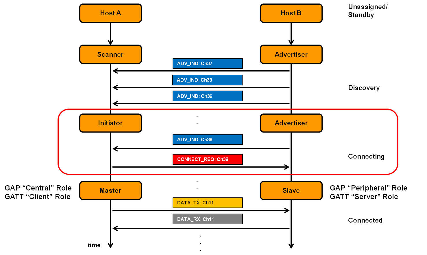
- A peripheral is either advertising or in a connection.
- A central is scanning and in one or more connections.
- This is not actually true; devices can be in many roles simultaneously
While in a connection, both devices act like servers; either device can read/write fields available on the other device.
Choosing a Data Channel for Communication
- Why do you switch from advertising channel to data channel?
- For better reliability and to improve quality of service
- How to pick a channel out of the 37 data channels?
- Randomize for reduced chance of collision
- What if two pairs pick same channel?
- Higher chance of collision occurring
- Some way to not be tied to the same data channel is needed
Frequency Hopping Spread Spectrum (FHSS)
- Connected devices hop through channels to improve reliability
- Recall each channel is MHz wide and there are channels. Three are used for advertising. So, frequency hopping follows
- Which exact channels are used and in what order might vary.
- For a hopping to be successful, both central/peripheral must agree on
- Follow same hop sequence (which channels to use and order to follow)
- Hop at a given time schedule
- Agree on when to schedule their first communication
- Some synchronization is needed!
- This information is sent on the
CONNECT_REQpacket. See Advertisement Packet Layering. In particular, this in the LLData of the Payload.
LLData:
| Name | Size |
|---|---|
| AA | octets |
| CRCInit | octets |
| WinSize | octet |
| WinOffset | octets |
| Interval | octets |
| Latency | octets |
| Timeout | octets |
| ChM | octets |
| Hop | bits |
| SCA | bits |
Connection Timing
BLE Connections happen on a Connection Interval. Some data is exchanged at each interval:
- acknowledgements
- additional packets can be sent if there is a lot to transmit
- Each interval is on the next channel in the hopping sequence, i.e. on the next interval, we use the next interval.
- Peripheral can skip a number of intervals to save energy, as defined in
Latencyconnection request parameter of theCONNECT_REQ→LLData→Latency. - These connection “events” happen at periodic intervals.
How do we schedule the very first connection event?
- WinOffset: Time from now until first event. “Let’s meet hours from now!”
- WinSize: Flexible window of time to expect first transmission. “I might be up to minutes late.” This is like an “anchor” for the TDMA schedule for this device.
How do you agree on hopping pattern?
Use the ChM and Hop to define the FHSS pattern.
- ChM: Map of which channels to use
- Hop: next hop increment. See Frequency Hopping Spread Spectrum (FHSS) modulo formula.
Ensuring Reliability
Connection Messages are sequenced for additional reliability. We can see this in the header of the PDU.
| Field Name | Size |
|---|---|
| LLID | bits |
| NESN | bit |
| SN | bit |
| MD | bit |
| RFU | bits |
| Length | bits |
- In the header of the PDU, there are two fields:
- NESN: Next Expected Sequence Number
- SN: Sequence Number
sequenceDiagram
    participant A as Device A
    participant B as Device B

    Note left of A: 1. Packet sent
    A->>B: SN=0
    Note right of B: 2. Packet received, CRC check passed<br/>3. Packet acknowledged
    B->>A: NESN=1
    Note left of A: 4. Acknowledgment received

    Note left of A: 5. Packet sent
    A->>B: SN=1
    Note right of B: 6. Packet received, CRC check <br/>passed, identified as new packet<br/> due to SN matching expected NESN<br/>7. Packet acknowledged
    B->>A: NESN=0
    Note left of A: 8. Acknowledgment received
An example of a successful acknowledgment. Sometimes we fail.
Scenario 1: Lost Acknowledgment or CRC Failure on ACK
In this case, Device receives the packet and validates the CRC. However, Device did not receive it or CRC failed.
sequenceDiagram
    participant A as Device A
    participant B as Device B

    Note left of A: 1. Packet sent
    A->>B: SN=0
    Note right of B: 2. Packet received,<br/> CRC check passed
    Note right of B: 3. Packet acknowledged
    B-->>A: NESN=1 (X - Lost/Failed)
    Note left of A: 4. Acknowledgment not received<br/>or CRC check failed

    Note left of A: 5. Packet resent
    A->>B: SN=0
    Note right of B: 6. Packet received, CRC check passed<br/>Identified as retransmission<br/> (SN != expected NESN)
    Note right of B: 7. Packet acknowledged
    B->>A: NESN=1
    Note left of A: 8. Acknowledgment received
Scenario 2: CRC Check Fail on Initial Packet
Here, receives the packet, but the CRC validation failed. It sends no acknowledgment to .
sequenceDiagram
    participant A as Device A
    participant B as Device B

    Note left of A: 1. Packet sent
    A->>B: SN=0
    Note right of B: 2. Packet received, <br/>CRC check failed<br/>No acknowledgment sent
    Note left of A: 3. Acknowledgment not received

    Note left of A: 4. Packet resent
    A->>B: SN=0
    Note right of B: 5. Packet received, <br/> CRC check passed
    Note right of B: 6. Packet acknowledged
    B->>A: NESN=1
    Note left of A: 7. Acknowledgment received
Link Layer ID
The LLID of the header tells the peripheral the control payload. There are many but some examples are:
- request update to connection parameters like interval (by peripheral)
- begin encrypting communication
- terminate a connection
LL_TERMINATE_INDThese are all handled by the link layer and not passed up.
Timeout Field
The timeout field is how long since hearing from a device before the connection breaks.
Although Link Layer ID has a terminate control, this field is useful in case if a device just wanders away, or is shut off, reprogrammed, etc.
Connection Performance
We care about robustness, performance, and scalability.
- Only the central needs to know the whole schedule of every peripheral. Central sends first packet at each connection interval to synchronize each peripheral.
- The BLE specification describes how a peripheral must “widen” its listening window based on Source Clock Accuracy. I.e. the clock may drift, so widening ensures it will still receive the packet
- We can schedule with granularity of at least ms, so devices per second.
- Since intervals can go up to seconds, we can have devices per max interval.
- Central can skip intervals without dropping the connection more granularity.
- So many thousands of devices (although we are sending the minimum-sized packet each time)
- The limit is much lower on real devices.
- often done in firmware
- limited by memory and complexity
Even though PHY can support Mbps, the actual maximum throughput is much lower. If we
- decrease connection interval as much as possible (iOS: ms, Android: ms)
- increase to the maximum packet size
- use the Data Length Extension (DLE) in BLE v4.2+ we only get bytes of useful data per connection event. Thus, we get
In practice it’s lower due to lost packets.